Undercarriage maintenance represents about half your total excavator maintenance costs over equipment life. Complete replacements vary widely by machine size. Check current pricing with service providers in your area, as costs change frequently.
Proper maintenance can extend component life substantially. Daily cleaning. Correct tensioning. Regular lubrication. This transforms a major expense into manageable, predictable costs.
The undercarriage bears the machine’s entire weight plus additional load from the bucket and material. It provides mobility across challenging terrain. Mud. Rock. Sand. Steep slopes. The system operates in the harshest conditions. Accumulates debris constantly. Creates cascading failures when neglected.
This guide covers daily cleaning procedures, wear assessment, proper operating techniques, and cost-effective service scheduling. You’ll discover excavator maintenance and repair resources that actually extend component life and maintain peak machine performance.
Important: Undercarriage component specifications, maintenance intervals, and replacement costs vary significantly by manufacturer, machine size, model year, and operating conditions. Always consult your equipment manual and verify current information with qualified service professionals. Prices mentioned are approximate ranges based on general market conditions and change frequently. Individual results vary based on equipment condition, operating environment, and maintenance practices. Regional pricing differences can be substantial – check with local suppliers for current costs.
Power Your Business with STM Trucks & Machinery
Whatever the size of your business, our experienced sales team will help you get the best from your budget.
Understanding Excavator Undercarriage Components and Their Functions
The undercarriage is a complex system. Multiple components work together under extreme stress. Understanding what each part does and common excavator engine troubleshooting helps you spot problems early. Prevents expensive failures. Let’s break down the main components and how they interact.
Track Chains and Shoe Assembly Systems
Track chains consist of pin and bushing assemblies. Hardened steel pins. Bronze or steel bushings. They connect individual track shoes into continuous loops. Pins transfer loads between shoes during digging operations and impact loading. Bushings provide wear surfaces for sprocket engagement.
Track shoes distribute machine weight whilst providing traction. Rubber pads or steel grousers, depending on application.
Chain stretch occurs as pins and bushings wear. Metal-to-metal contact. Abrasive contamination. Elongation accumulates over time. Eventually requires adjustment or replacement when elongation exceeds specifications.
Monitoring chain pitch provides early warning of wear progression. Enables planned replacements. Prevents unexpected failures.
Rollers, Idlers, and Sprocket Functions
Bottom rollers support the machine weight whilst guiding track alignment through flanged edges. They operate in sealed bearing housings. Filled with lubricating oil. Protected by dual seals against contamination.
Carrier rollers support track return sections. They prevent sagging that creates stress concentrations. Maintains proper track geometry. Without carrier support, you get excessive sag. That accelerates pin and bushing wear dramatically.
Idler wheels maintain track tension. Guide track loops around the frame ends.
Drive sprockets transfer power from final drives to track chains through precise engagement with bushings. The tooth profile meshes with the bushing outer diameter. Creates power transfer through friction and mechanical interference.
Sprocket tooth wear affects power transmission efficiency. Creates uneven loads that accelerate chain wear.
Drive Motor and Final Drive Components
Drive motors convert hydraulic power into rotational motion. Final drives provide speed reduction through planetary gear systems. Torque multiplication from motor output to final output at travel speeds.
Planetary gear systems within final drives operate in oil baths. Require periodic service for proper performance.
Drive motor failures often result from contamination. Particles damage precision surfaces. Overloading causes seal failure and component fracture. Inadequate maintenance allows oil degradation. Water contamination. Inadequate lubrication.
Understanding operating pressures and temperature limits helps prevent failures. Check your operator manual for specific limits for your machine model.
Daily Cleaning Procedures and Debris Management
Daily cleaning is your first line of defence against undercarriage wear. Debris trapped in tracks acts like grinding paste. Accelerates component wear dramatically. Proper cleaning techniques remove contamination without damaging seals or bearings. Here’s how to do it right.
Effective Cleaning Techniques and Equipment
Pressure washing provides efficient debris removal. Completes full undercarriage cleaning quickly. But requires proper techniques to avoid component damage.
Water pressure limits matter. Don’t exceed the maximum recommended PSI. Hold nozzles at a safe distance from seals and bearings. Maintain a safe distance to prevent seal damage from concentrated water jets. Direct high-pressure spray can displace seals. Force water past barriers into bearing cavities. Causes premature failure.
Hot water improves cleaning effectiveness for sticky materials. Clay. Mud. Grease. Organic debris. Reduced viscosity. Improved detergent action. Reduces time requirements. Saves labour costs.
Manual cleaning using shovels and scrapers addresses packed debris that pressure washing cannot remove. Begin cleaning from the centre. Work outward. Complete debris removal from roller interfaces and chain engagement areas.
Safety considerations include proper personal protective equipment. Awareness of hydraulic system pressure. Environmental compliance for wash water disposal. Contaminated runoff requires containment and proper disposal. Check current local environmental regulations, as requirements vary by region.
Post-Work Cleaning Protocols
End-of-shift cleaning routines prevent overnight debris hardening. Mud and clay cure after drying. Makes subsequent removal complicated. Requires longer cleaning time. Aggressive techniques risk component damage. Incomplete removal leaves residual contamination.
Quick inspections during cleaning identify developing problems. Loose components. Track shoe bolts may loosen after operation. Oil leaks are showing seal failure. Abnormal wear patterns. Uneven roller wear. Sprocket tooth hooking. Track shoe edge wear. All indicate misalignment or improper tension.
Most operators skip this step. Then they wonder why small problems become expensive failures. Don’t be that person.
Documentation of cleaning activities and observed conditions provides historical data. Supports maintenance planning and warranty claims. Simple log entries noting debris type, cleaning time, and observed conditions support better maintenance programmes.
Track Tension Adjustment and Maintenance Procedures
Proper track tension is critical for undercarriage life. Too tight and you stress the components unnecessarily. Too loose and you risk track jumping or derailment. Getting it right requires accurate measurement and careful adjustment. Here’s what you need to know.
Measuring Track Tension and Sag
Track sag measurement provides the most reliable tension indication. Measured as vertical distance from track bottom to reference line. At the midpoint between rollers. With the machine on level ground. Tracks raised using excavator hydraulics to eliminate ground contact.
Specifications vary by machine size. Mini excavators need less sag. Large excavators need more. Check your operator manual for specific sag specifications for your machine model.
Over-tension below minimum sag increases component wear. Under-tension exceeding maximum sag risks track jumping and derailment. Neither is good.
Measurement procedures require the machine to be stationary. Tracks are properly supported. Use straight edges or tensioned strings to establish reference lines. Measure perpendicular distance from the track surface to the reference line at specified locations.
Adjustment Procedures and Safety Considerations
Hydraulic tensioning systems use grease pumps to extend or retract tension cylinders. Grease addition extends cylinders to increase tension. Reduces sag. Grease removal through the release valve retracts the cylinders to decrease tension. Increases sag.
Adjustment requires adding or removing grease through dedicated fittings. Monitor sag measurements continuously during adjustment.
Never exceed maximum pressure specifications. Over-pressurisation can cause component failure. Cylinder seal rupture. Grease line burst, creating contamination and a safety hazard. Frame damage at mounting points. Check current repair costs with service providers, as prices vary significantly by region.
Safety procedures include stable machine support. Proper tools. Follow manufacturer lockout procedures. Tensioning systems store huge amounts of energy. It can cause serious injury if released unexpectedly.
Trust me, you don’t want to learn this the hard way.
Component Wear Assessment and Measurement Techniques
Regular wear measurement is how you catch problems early. Before they become expensive. Precision measurement tells you when components need replacement. Prevents unexpected failures. Enables planned maintenance during scheduled downtime. Here are the key measurements to track.
Track Chain and Pin Measurement Procedures
Pin diameter measurement requires precision instruments. Inside micrometres. Bore gauges with dial indicators. Compare actual measurements against new specifications. Wear limits vary by machine size.
Measure at multiple points. Identifies uneven wear patterns. That indicates alignment problems or inadequate lubrication. Compare measurements against manufacturer specifications. Determines replacement timing.
Chain pitch elongation occurs as pins and bushings wear. Accumulates over operating hours. Normal conditions versus severe conditions show different wear rates. Eventually requires tension adjustment or chain replacement.
Measure pitch over multiple links. Obtain accurate averages. Compare against specifications to assess wear progression. Verify current replacement costs with parts suppliers before budgeting.
Roller and Sprocket Wear Evaluation
Roller diameter measurement tracks wear progression from the new diameter declining to the replacement limit. Predict replacement timing when wear reaches the allowable limit. Replace before maximum wear to prevent sudden failure.
Measure at multiple circumferential locations. Identifies uneven wear. That indicates misalignment or contamination problems.
Oil leak detection around roller seals indicates bearing deterioration. Contamination allows abrasive particles into the bearing cavity. Seal wear from normal operation. Impact damage from rock strikes or severe loading. Requires attention before complete bearing failure causes roller seizure and potential track damage.
Sprocket tooth wear assessment involves measuring tooth thickness at engagement points. Compare against specifications. Uneven wear patterns indicate chain or alignment problems requiring correction.
Operating Techniques That Reduce Undercarriage Wear
How you operate your excavator matters as much as maintenance. An aggressive operation accelerates wear dramatically. Smart operating techniques extend component life substantially. Often doubles the undercarriage life compared to abusive operation. Here’s what makes the difference.
Proper Turning and Travel Techniques
Wide turning reduces track scrubbing. Reduces component stress compared to pivot turns. Pivot turns create maximum wear conditions. Lateral forces. Track shoe wear rates are multiple times higher than straight travel.
Plan travel routes to minimise tight turns, particularly on abrasive surfaces that accelerate track wear.
Smooth acceleration and deceleration prevent impact loading. Stresses drivetrains. Track components. Gradual speed changes distribute loads more evenly. Reduces peak stresses that cause premature failures.
Look, this seems obvious. But watch operators on site. They treat excavators like sports cars. Aggressive turns. Hard acceleration. Then they complain about undercarriage costs.
Slope operation requires specific techniques. Prevents track slippage and excessive wear. Position the drive motors at the rear when climbing slopes. Better traction. Reduced slippage.
Job Planning and Setup Strategies
Site preparation reduces unnecessary travel and repositioning. That accumulates undercarriage wear without productive output. Travel consumes wear equivalent to hours of stationary digging operations. Repositioning moves add distance per incident in poorly planned sites.
Plan material placement and machine positioning. Minimise travel distances. Maintain efficient workflow.
Travel route planning avoids unnecessary exposure to abrasive surfaces and obstacles. When possible, use established roadways or prepared surfaces. Not cross-country travel over rough terrain.
Scheduled Maintenance Intervals and Service Procedures
Regular inspection schedules catch problems before they escalate. Daily checks take minutes but prevent major failures. Weekly inspections provide detailed wear tracking. Periodic service addresses developing issues. Here’s how to structure your inspection programme.
Daily and Weekly Inspection Routines
Daily visual inspections before the operation start focus on obvious problems. Loose components. Track shoe bolts require a torque check. Oil leaks indicate seal failure. Visible damage. Cracked shoes. Bent guards. Damaged seals. Sprocket tooth breakage.
These quick checks take minutes. Prevent many expensive failures. Identify problems before they progress.
Weekly detailed inspections include measurement checks. Track sag. Roller diameter showing wear progression. Sprocket tooth thickness. Lubrication point service. Greasing points. Comprehensive visual assessment.
Document findings. Schedule corrective actions based on severity and operational requirements.
Periodic Service and Component Replacement
Major service intervals involve a thorough system evaluation. Measuring all wear points. Inspecting bearing condition. Checking seal integrity. Assessing alignment.
Component replacement based on wear limits. Replace items approaching maximum allowable wear. Prevents secondary damage. Professional diagnostic assessment for complex problems. Final drive noise. Unusual wear patterns. Recurring failures.
When complex undercarriage diagnostics exceed in-house capabilities, working with established service providers like STM Trucks & Machinery gives you access to specialised measurement equipment, genuine replacement parts, and technical expertise that protects your investment.
Schedule these services during planned downtime. Minimises operational disruption.
Component replacement timing balances use against failure risk. Economic analysis guides replacement decisions. Replace components approaching wear limits during scheduled downtime. Not risk unexpected failures. Verify current component costs before making replacement decisions, as prices vary significantly.
Lubrication Systems and Grease Management
Proper lubrication is critical for undercarriage life. Inadequate greasing causes rapid wear. Excessive greasing attracts contamination. Finding the right balance requires understanding grease points, application techniques, and service intervals. Here’s what you need to know.
Manual Greasing Procedures and Intervals
Grease point identification requires understanding component locations. Track pins at each link joint. Roller bearings at each roller end. Idler pivots. Sprocket hubs. Tension cylinder pivots. Access procedures matter. Some points require machine positioning. Guard removal. Track rotation to expose fittings.
Some points require machine positioning or panel removal for access. Makes thorough approaches needed for complete coverage.
Application quantities depend on component size and operating conditions. Over-greasing causes problems. Seal damage is displacing seals from grooves. Contamination attraction where excess grease collects dirt and abrasive particles. Creates a grinding paste that accelerates wear.
Apply grease until fresh lubricant appears at sealing points. Then remove excess. Prevents contamination buildup.
Greasing intervals vary by component and operating severity. Daily service for pins and bushings in severe conditions. Mud. Sand. High use. Weekly service for moderate conditions. Contaminated environments require shortened intervals.
Automatic Lubrication System Benefits
Automatic systems provide consistent lubrication. Deliver measured grease quantities at programmed intervals, regardless of operator attention or workload pressures. Manual lubrication often gets skipped or done inadequately. Automatic systems eliminate human error. Reduce labour requirements.
Installation costs can be recovered within months through reduced labour. Extended component life. Eliminated under-lubrication failures. Systems include monitoring capabilities. Alert operators to malfunctions or low grease levels.
Smart operators won’t run equipment without them anymore. The investment pays back fast.
Essential Tools and Equipment for Undercarriage Maintenance
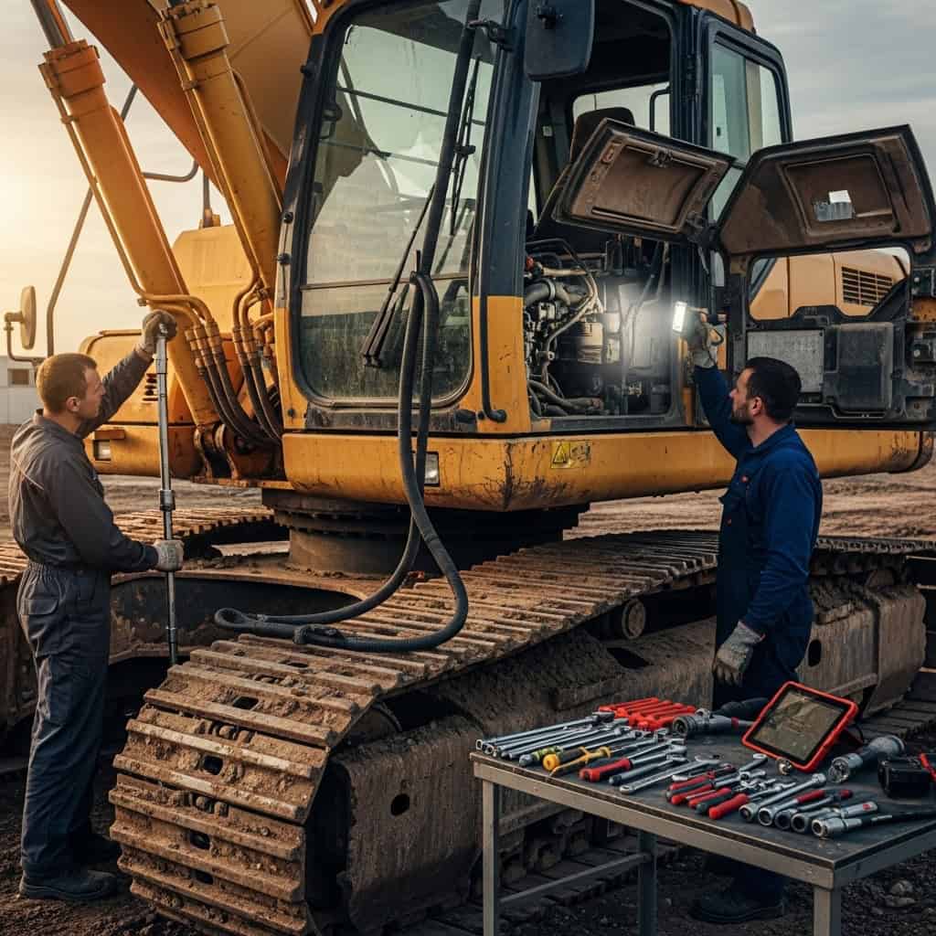
Precision measuring instruments enable accurate wear assessment and component evaluation. Micrometres for pin diameters and roller dimensions. Bore gauges for the internal bushing bore. Dial indicators for sag and alignment.
Accurate wear assessment determines replacement timing. Prevents premature replacement of unnecessary parts. Prevents delayed replacement, causing secondary damage. Digital instruments often provide better accuracy and data recording capabilities.
Grease guns and lubrication equipment must provide consistent application quantities. Access difficult locations. Flexible hoses. Angled fittings for confined spaces around track assemblies.
Battery-powered guns offer convenience. Manual guns provide better pressure control for sensitive applications.
Hydraulic tools for track tensioning require proper pressure ratings and safety features. Use only manufacturer-approved tools and procedures. Prevents component damage or personal injury from high-pressure systems.
Maximising Undercarriage Life Through Smart Care
Smart undercarriage maintenance transforms reactive problem-solving into proactive asset management. Daily cleaning. Correct tensioning checks weekly. Measurement programmes are monthly. Proper lubrication daily or per schedule.
Understanding component interactions enables predictive maintenance. These practical strategies for reducing excavator downtime prevent most failures.
The investment in thorough undercarriage maintenance programmes can provide substantial returns. Extended component life. Reduced downtime. Improved machine performance. Returns vary significantly based on equipment usage and operating conditions.
For professional undercarriage service, including component replacement, alignment verification, and wear assessment, reach out to STM Trucks & Machinery for expert service and local support.
Start using these maintenance practices immediately. Consistent execution of proven procedures addressing all aspects of undercarriage care will deliver reduced costs, improved reliability, and enhanced productivity for years to come.
Most operators ignore half this advice. Then they get shocked by replacement costs. Their machines spend weeks in the shop. Projects get delayed. Clients get angry.
Don’t be that operator.
Disclaimer: Undercarriage component specifications, wear limits, maintenance intervals, and replacement costs vary significantly by equipment manufacturer, machine size, model year, and operating conditions. Information in this guide reflects general maintenance principles. Always consult your equipment manual and qualified service professionals for specific maintenance procedures and component specifications. Costs mentioned are approximate ranges based on general market conditions and vary substantially by region, service provider, component quality, and specific circumstances. Always verify current pricing before budgeting for component replacement.